|
Seismo-VLAB
1.3
An Open-Source Finite Element Software for Meso-Scale Simulations
|


|
|
Seismo-VLAB
1.3
An Open-Source Finite Element Software for Meso-Scale Simulations
|
|
The Recorder class defines a solution output file. Currently, there are three object solution that can be recorded:
The Recorder main member functions are:
REFERENCE:
The python Pre-Analysis in the 01-Pre_Process/Method/Attach.py file provides with an interface to create a Recorder in JSON format. For example, we use:
addRecorder(tag, attributes):
Example
A RECORDER can be defined using the python interface as follows:
SVL.addRecorder(tag=1, attributes={'name': 'PARAVIEW', 'file': 'Animation.out', 'ndps': 8})
SVL.addRecorder(tag=2, attributes={'name': 'NODE', 'file': 'Displacement.out', 'ndps': 8, 'resp': 'disp', 'list': [25, 26, 32]}) SVL.addRecorder(tag=3, attributes={'name': 'SECTION', 'file': filename, 'resp': 'stress', 'ndps': 8, 'coords': [zi, yi], 'list': 1})
Application
Please refer to any python file located at 03-Validations/01-Debugging/ to see an example on how to define a Recorder using the python interface.
On the contrary, the 01-Pre_Process/Method/Remove.py file provides with an interface to depopulate the Entities dictionary. For example, to remove an already define Recorder, use:
The C++ Run-Analysis in the 02-Run_Process/12-Utilities/Recorder.cpp file provides the class implementation. A Recorder is created using the built-in json parse-structure provided in the Driver.hpp. A Recorder is defined inside the "Recorders" json field indicating its "Tag". However, depending on the recorded object response, it will be the required fields to be specified.
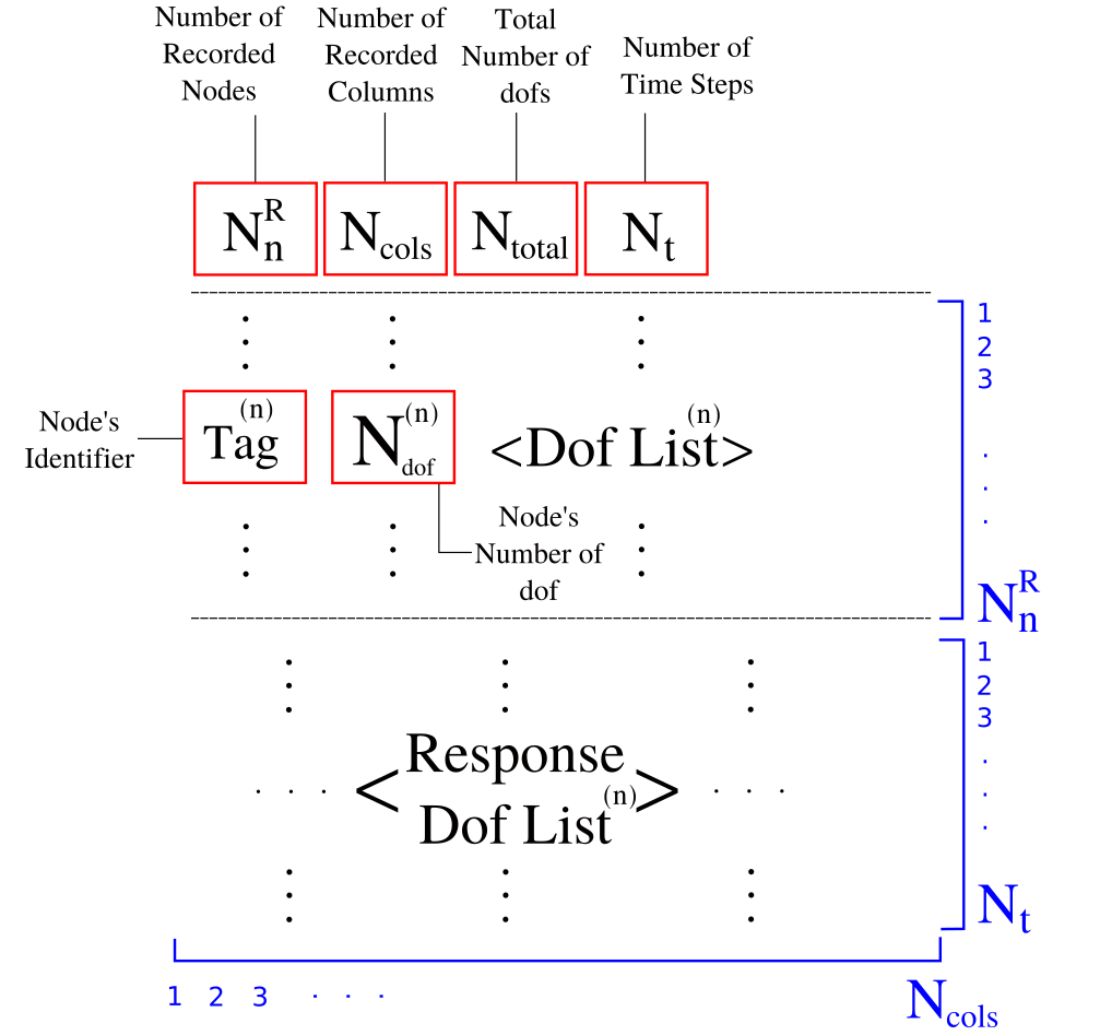
A NODE Recorder can be created using the built-in parse-function provided in the Parser as follows,
 {
    "Recorders": {
        "Tag": {
            "name": "NODE",
            "file": str,
            "ndps": int,
            "resp": str,
            "nsamp": int,
            "list" : [ ],
        }
    }
}
| Variable | Description |
|---|---|
file | The file name where the results are going to be stored. |
resp | Depend on the object, see the NOTE below. |
nsamp | The number of sampling points (dynamics analysis) to record the solution. |
ndps | The precision number to store the results. |
list | The list of Node identifiers. |
resp= disp, vel, accel, reaction.An ELEMENT Recorder can be created using the built-in parse-function provided in the Parser as follows,
{
    "Recorders": {
        "Tag": {
            "name": "ELEMENT",
            "file": str,
            "ndps": int,
            "resp": str,
            "nsamp": int,
            "list" : [ ],
        }
    }
}
| Variable | Description |
|---|---|
file | The file name where the results are going to be stored. |
resp | Depend on the object, see the NOTE below. |
nsamp | The number of sampling points (dynamics analysis) to record the solution. |
ndps | The precision number to store the results. |
list | The list of Element identifiers. |
internal force has the structure showed in the Figure below. 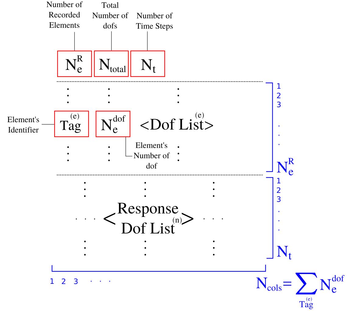
stress/strain/strainrate has the structure showed in the Figure below. 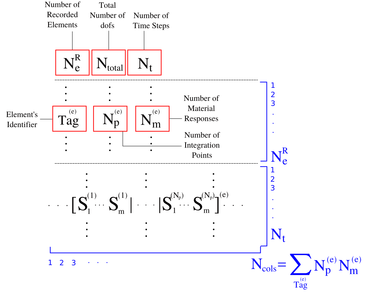
response=strain, stress, internalforce, strainrate.An SECTION Recorder can be created using the built-in parse-function provided in the Parser as follows,
{
    "Recorders": {
        "Tag": {
            "name": "SECTION",
            "file": str,
            "ndps": int,
            "resp": str,
            "nsamp": int,
            "coords": [ ],
            "list" : [ ],
        }
    }
}
| Variable | Description |
|---|---|
file | The file name where the results are going to be stored. |
resp | Depend on the object, see the NOTE below. |
nsamp | The number of sampling points (dynamics analysis) to record the solution. |
ndps | The precision number to store the results. |
coords | Vector with the section coordinates. |
list | The list of Element identifiers. |
response = strain, stress are allowed, and they are computed at each integration point.An PARAVIEW Recorder can be created using the built-in parse-function provided in the Parser as follows,
{
    "Recorders": {
        "Tag": {
            "name": "PARAVIEW",
            "file": str,
            "ndps": int,
            "nsamp": int,
            "features" : int,
        }
    }
}
| Variable | Description |
|---|---|
file | The file name where the results are going to be stored. |
nsamp | The number of sampling points (dynamics analysis) to record the solution. |
ndps | The precision number to store the results. |
features | The number of features (for elements) to be written in paraview (computed using Pre-Analysis). |
Animation_PARTp.q.vtk, where p represents the partition number (starting from 0 to np), and q the solution number (starting from 0 to nTimeSteps/nsample). nsamp = n means the paraview solution will be stored every n time steps. Paraview files are heavy and a default sampling rate of five is assumed. features = n means that the number of connectivities with its length of all elements in the partition is n. This parameter is internally used in Paraview.  1.8.13.