|
Seismo-VLAB
1.3
An Open-Source Finite Element Software for Meso-Scale Simulations
|


|
|
Seismo-VLAB
1.3
An Open-Source Finite Element Software for Meso-Scale Simulations
|
|
The Node class defines a point in a finite element mesh. This class provides with member functions that allow
This class also provided with private member variables that stores information regarding
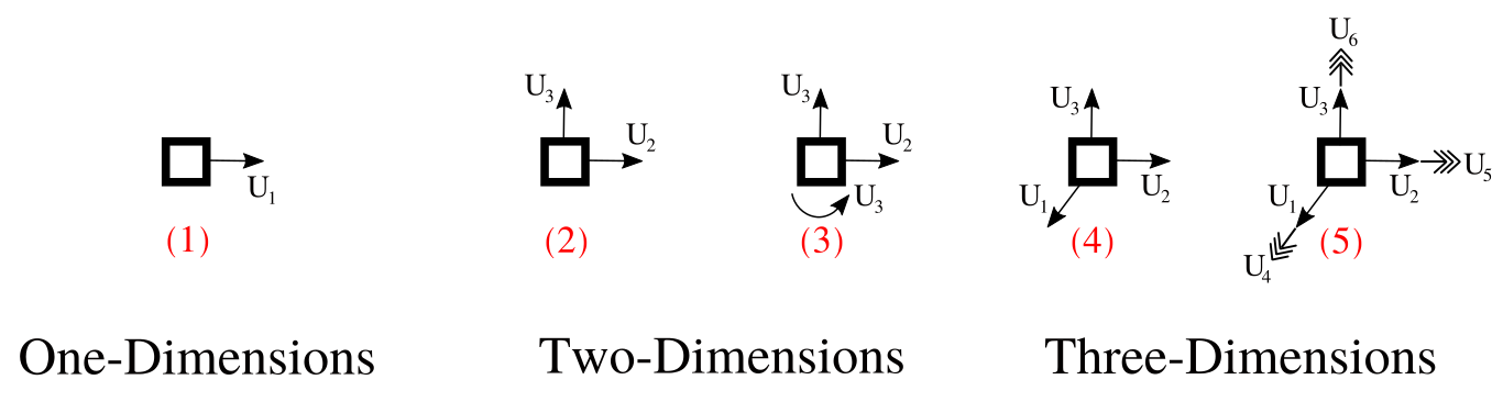
The Figure below shows a schematic representation of a node in 1 dimension, 2 dimensions and 3 dimensions, respectively. The single arrows represent the translational degree-of-freedom, while the triple arrows represent the rotational degree-of-freedom.
REFERENCE:
The python 01-Pre_Process/Method/Attach.py file provides with an interface to populate the Entities dictionary. A Node can be created using the addNode() function. This function will transform the provided information into json format to be parse in the Run-Analysis.
addNode(tag, ndof, coords, freedof, totaldof):
Example
A NODE can be defined using the python interface as follows:
SVL.addNode(tag=6, ndof=3, coords=[1.00, 0.00, 0.00])
Application
Please refer to the D05-ST_Lin_2DBernoulliArc_Elastic_Frame2.py file located at 03-Validations/01-Debugging/ to see an example on how to define nodes using the addNode function.
On the contrary, the 01-Pre_Process/Method/Remove.py file provides with an interface to depopulate the Entities dictionary. For example, to remove an already define Node, use:
The C++ 02-Run_Process/01-Node/Node.cpp file provides with the Node class implementation. A Node is created using the built-in json parse-structure provided in the Driver.hpp. A Node is defined inside the "Nodes" json field indicating its "Tag" as follows,
{
    "Nodes": {
        "Tag": {
            "ndof" : int,
            "totaldof": [ ],
            "freedof" : [ ],
            "coords"  : [ ]
        }
    }
}
| Variable | Description |
|---|---|
Tag | A unique node number identifier. |
ndof | Number of degree-of-freedom in the node. |
totaldof | List of total degree-of-freedom identifiers. |
freedof | List of free degree-of-freedom identifiers, ( \(= -1\)) is restrain, ( \(\leq -2\)) is constraint, and and ( \(\geq 0\)) is free. |
coords | The coordinates in 1-, 2-, and 3-dimensions of the node. |
totaldof and freedof defines the sparse matrix pattern. ndof at each node is defined by the user, and such number should be consistent with the element that will be connected to that node. Defining the number of degree of freedom in this manner allows to add explicitly internal degree of freedom that can be used to formulate elements, see for instance PML2DQuad4.A fixed tri-dimensional NODE with 3 degree of freedom and coordinate (0.0, 0.0, 10.5)
{ "Nodes": { "4": { "ndof" : 3, "totaldof": [12, 13, 14], "freedof" : [-1, -1, -1], "coords" : [0.0, 0.00, 10.50] } } }A free two-dimensional NODE with 3 degree of freedom and coordinate (0.20, 0.50)
{ "Nodes": { "48": { "ndof" : 3, "totaldof": [345, 346, 347], "freedof" : [327, 328, 329], "coords" : [0.20, 0.50] } } }
 1.8.13.