|
Seismo-VLAB
1.3
An Open-Source Finite Element Software for Meso-Scale Simulations
|


|
|
Seismo-VLAB
1.3
An Open-Source Finite Element Software for Meso-Scale Simulations
|
|
The FIB3DLINESECTION (or FIB2DLINESECTION) class creates a fiber line Section class that have different behavior at each Fiber. In general, a Fib2DLineSection or Fib3DLineSection can represent the geometry of any cross section.
The section properties are:
REFERENCE:
The python Pre-Analysis in the 01-Pre_Process/Method/Attach.py file provides with an interface to create a general fiber section. For example the Patch and Layer allow to construct any general section geometry.
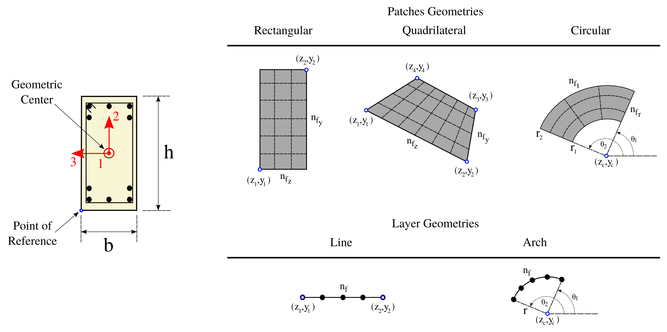
Define a RECTANGULAR PATCH using the following dictionary structure,
"patch": {
      "Tag": {
          'name' : 'RECTANGULAR',
          'fiber' : int,
          'nfibz' : int,
          'nfiby' : int,
          'coords' : [[z1,y1],[z2,y2]]
      }
}
where 'fiber' is the fiber identifier the patch is made of, 'coords' is a list with the coordinates of the lower-left corner and the upper-right corner, 'nfibz' and 'nfiby' the number of fibers in \(x_3\) and \(x_2\) respectively.
Example
Create the reinforced concrete layers showed in figure above
patch = {
'1': {'name': 'RECTANGULAR', 'fiber': 1, 'nfibz': 5,'nfiby': 30, 'coords': [[z1,y1],[z2,y2]]},
'2': {'name': 'RECTANGULAR', 'fiber': 2, 'nfibz': 3,'nfiby': 5, 'coords': [[z3,y3],[z4,y4]]},
'3': {'name': 'RECTANGULAR', 'fiber': 2, 'nfibz': 3,'nfiby': 5, 'coords': [[z5,y5],[z6,y6]]}
}
"patch": {
      "Tag": {
          'name' : 'CIRCULAR',
          'fiber' : int,
          'nfibr' : int,
          'nfibt' : int,
          'center' : [zc, yc],
          'coords' : [[r1,t1],[r2,t2]]
      }
}
where 'fiber' is the fiber identifier the patch is made of, 'coords' is a list with the coordinates of the lower-left corner and the upper-right corner, 'nfibr' and 'nfibt' the number of fibers in radial and angular direction respectively.
Define a LINE LAYER using the following dictionary structure,
"layer": {
      "Tag": {
          'name' : 'LINE',
          'fiber': int,
          'nfib' : int,
          'area' : double,
          'coords' : [[z1,y1],[z2,y2]]
      }
}
where 'fiber' is the fiber identifier the layer is made of, 'coords' is a list with the coordinates of the initial and end points of the line, 'nfib' the number of fibers layers along the line.
Example
Create the steel layers showed in figure above
layer = {
'1': {'name': 'LINE', 'fiber': 3, 'nfib': 3, 'area': 1.0, 'coords': [[z1,y1],[z2,y1]]},
'2': {'name': 'LINE', 'fiber': 3, 'nfib': 2, 'area': 1.0, 'coords': [[z1,y2],[z2,y2]]},
'3': {'name': 'LINE', 'fiber': 3, 'nfib': 2, 'area': 1.0, 'coords': [[z1,y3],[z2,y3]]},
'4': {'name': 'LINE', 'fiber': 3, 'nfib': 3, 'area': 1.0, 'coords': [[z1,y4],[z2,y4]]}
}
"layer": {
      "Tag": {
          'name' : 'ARCH',
          'fiber': int,
          'nfib' : int,
          'area' : double,
          'radius': double,
          'angle' : [t1,t2],
          'center' : [zc, yc]
      }
}
where 'fiber' is the fiber identifier the layer is made of, 'coords' is a list with the coordinates of the initial and end points of the line, 'nfib' the number of fibers layers along the line.
This information is then used to create a Fib2DLineSection or Fib3DLineSection section using json format as follows:
addSection(tag, name='Fib3DLineSection', model='Fiber', attributes):
Example
A FIB3DLINESECTION section can be defined using the python interface as follows:
SVL.addSection(tag=1, name='Lin2DRectangular', model='Plain', attributes={'b': 0.25, 'h': 0.75, 'patch': patch, 'layer': layer})
Application
Please refer to the D24-DY_WideFlange_Linear_Fiber_Section_Frame2.py or D25-DY_WideFlange_NonLinear_Fiber_Section_Frame2.py files located at 03-Validations/01-Debugging/ to see an example on how to define a Fib3DLineSection section.
On the contrary, the 01-Pre_Process/Method/Remove.py file provides with an interface to depopulate the Entities dictionary. For example, to remove an already define Section, use:
The C++ Run-Analysis in the 02-Run_Process/03-Sections/01-Plain/Lin3DRectangular.cpp file provides the class implementation. A Lin3DRectangular section is created using the built-in json parse-structure provided in the Driver.hpp. A Lin3DRectangular is defined inside the "Sections" json field indicating its "Tag" as follows,
{
    "Sections": {
        "Tag": {
            "name" : "FIB3DLINESECTION",
            "model" : "FIBER",
            "attributes": {
                "zi": [ ],
                "yi": [ ],
                "Ai": [ ],
                "fiber": [ ],
                "kappa2": double,
                "kappa3": double,
                "ip": int,
                "theta": double
            }
        }
    }
}
| Variable | Description |
|---|---|
Tag | Unique Section object identifier. |
zi | Vector with the \(x_3\) coordinate of each fiber. |
yi | Vector with the \(x_2\) coordinate of each fiber. |
Ai | Vector with the area of each fiber. |
kappa2 | Cross section shear factor along x2 local axis |
kappa3 | Cross section shear factor along x2 local axis |
ip | The insertion point, see Insertion Point. |
theta | The section rotation angle, see Local Axes. |
fiber | Vector of identifier of each fiber. |
ip=10 and theta=0.0A FIB3DLINESECTION section of height 0.75, width 0.25 and made of fiber 1 and discretized in three areas is defined:
{ "Sections": { "1": { "name" : "FIB3DLINESECTION", "model": "FIBER", "attributes": { "h" : 0.75, "b" : 0.25, "zi" : [0.125, 0.125, 0.125], "yi" : [0.125, 0.375, 0.625], "Ai" : [0.0625, 0.0625, 0.0625], "fiber": [1,1,1] } } } }
 1.8.13.