|
Seismo-VLAB
1.3
An Open-Source Finite Element Software for Meso-Scale Simulations
|


|
|
Seismo-VLAB
1.3
An Open-Source Finite Element Software for Meso-Scale Simulations
|
|
The option insertion point allows to place the center-line of the LINE Element in a different location. The options are shown in Figure below.
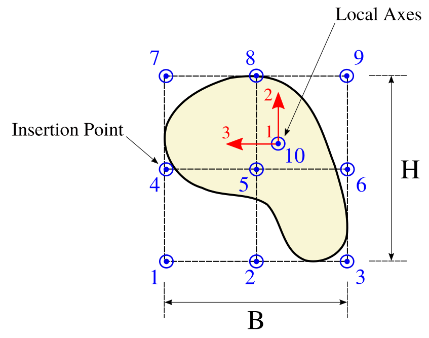
This generates changes in the section stiffness matrix, and they are considered using the following transformation matrix
\[ \mathbf{T}_\textrm{S} = \begin{bmatrix} 1 & x_3 & x_2 \\ 0 & 1 & 0\\ 0 & 0 & 1 \end{bmatrix}\,. \]
Thus, the resultant section stiffness matrix is obtained as
\[ \mathbf{K}_\textrm{S} = \mathbf{T}_\textrm{S}^\top \mathbf{K}_\textrm{c} \mathbf{T}_\textrm{S} \,, \]
where \(\mathbf{K}_\textrm{c}\) is the section stiffness matrix from the center-line, i.e., ip=10, and \(\mathbf{K}_\textrm{S}\) is the modified section stiffness matrix at the insertion point, and \(x_3, x_2\) are the coordinates with respect to ip=10 of the 3-axis and 2-axis.
ip=10, this is at the section geometric center. REFERENCE:
 1.8.13.