|
Seismo-VLAB
1.3
An Open-Source Finite Element Software for Meso-Scale Simulations
|


|
|
Seismo-VLAB
1.3
An Open-Source Finite Element Software for Meso-Scale Simulations
|
|
Section for frame elements also require the definition of a local coordinates system. This local axis transformation is performed depending on the Element.
theta represents the rotation in degrees about the 1-axis as shown in Figure: 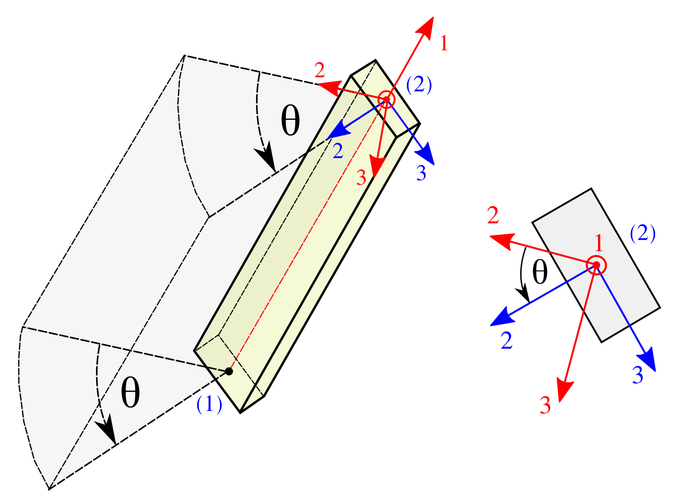
\[ \mathbf{T}_\textrm{S} = \begin{bmatrix} 1 & 0 & 0 \\ 0 & \cos \theta & \sin \theta \\ 0 & -\sin \theta & \cos \theta \end{bmatrix} \,. \]
This transformation is intended to be used for column/beam Element types.theta represents the rotation in degrees about the 3-axis as shown in Figure: 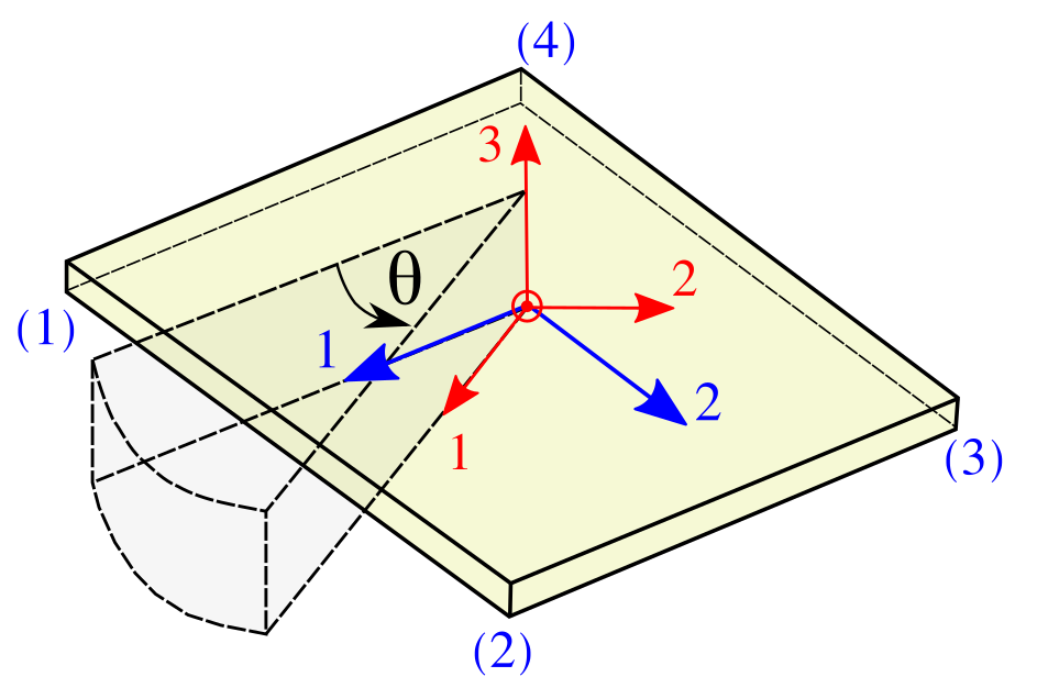
\[ \mathbf{T}_\textrm{S} = \begin{bmatrix} \cos \theta & \sin \theta & 0\\ -\sin \theta & \cos \theta & 0\\ 0 & 0 & 1 \end{bmatrix} \]
Then, for both cases the rotated local local axis are computes \(\hat{v}_\textrm{i} = \mathbf{T}_\textrm{S} \, v_\textrm{i}\), where \(v_\textrm{i}\) represents the local axis for \(\textrm{i} = 1,2,3\) (in red), and \(\hat{v}_\textrm{i}\) its transformed local axis (in blue).
theta is defines, then \(\theta = 0\) is assumed.  1.8.13.